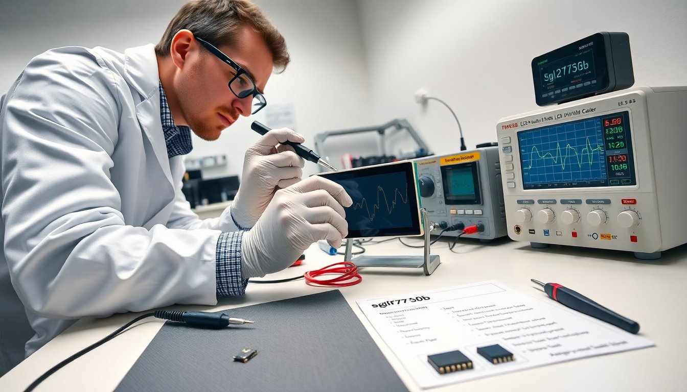
The sglf27t350b appears as a common LCD module used in many display projects and repairs. This guide lists key specs, common faults, and repair steps. It aims to help a technician identify parts, run tests, and decide when to replace components. The language stays direct. The instructions stay practical. The reader will find clear steps and parts data.
Table of Contents
ToggleKey Takeaways
- The sglf27t350b is a 2.7-inch TFT-LCD module commonly used in handheld and industrial devices with varying color depths and supply voltages.
- Technicians should prioritize visual inspection, power supply checks, and signal probing to diagnose common faults like no display, dim images, or flickering.
- Replacing parts such as the LED backlight strip, FPC cable, or controller module depends on symptom patterns and successful diagnostic testing.
- Maintaining the sglf27t350b involves careful cleaning, avoiding solvent damage, securing cables, and minimizing FPC cable bending to prevent intermittent faults.
- Ordering replacement parts requires matching the exact board revision and datasheet specs to ensure compatibility and repair success.
- Following step-by-step checks and using current-limited power supplies improves safety and helps keep the sglf27t350b module serviceable with minimal downtime.
Quick Overview And Key Specifications
The sglf27t350b refers to a 2.7-inch TFT-LCD module that appears in small handhelds and industrial panels. It uses an ST-compatible controller and supports 262K or 16.7M color depth depending on the panel revision. The module draws 120–250 mA in normal operation and 1–2 mA in standby. The typical supply voltage sits at 3.3 V for logic and 5 V for backlight, but some revisions use a 3.0 V LED supply. The module accepts parallel 8-bit data and SPI command modes. Its viewing angle measures 85° horizontally and 85° vertically in common spec sheets.
Mechanical specs match a 27 mm by 35 mm viewing area with a 320×240 pixel resolution in standard listings. The PCB includes pads for power, ground, data, reset, and a backlight enable. The connector type varies by vendor. It often ships with an FPC flexible cable or an 8-pin header. The glass front uses an anti-glare coating on some runs and a glossy finish on others.
Engineers should note the touch option. Some sglf27t350b boards include a capacitive or resistive touch layer. The touch interface uses I2C or analog lines. The touch layer changes the overall thickness and the pin mapping.
Designers should check the datasheet revision and part suffix. The same core name appears across several panels with small electrical differences. The safest approach reads the part marking and matches the vendor datasheet. The sglf27t350b name alone does not guarantee identical pinouts or LED voltage.
Common spare parts include backlight LEDs, the controller IC, and the FPC cable. Replacement backlight strips require voltage matching. The controller IC often uses standard driver chips that third-party suppliers can source. The listed operating temperature normally spans -20 °C to 70 °C. Storage limits usually extend from -40 °C to 85 °C.
Troubleshooting, Routine Maintenance, And Common Failure Modes
A technician finds many failures in connectors, backlight, and controller power rails. The first check inspects visible damage. The second check measures supply voltages. The third check tests data lines for proper timing. The common failure modes include no display, dim image, flicker, lines or artifacts, and touch failure.
No display often results from missing VCC, missing LED supply, or a failed controller. A quick test applies known-good 3.3 V to the logic pin and known-good LED voltage to the backlight. The module should respond with a brief LED flash or a voltage draw. If the module shows no sign, the controller may be dead.
Dim image usually points to low backlight voltage or degraded LEDs. The technician measures the LED string voltage under load. The LEDs should show near the rated string voltage. If the voltage reads low but the supply sits at expected value, the string may have open diodes or bad solder joints.
Flicker often indicates poor ground or fluctuating LED driver supply. The tester inspects ground returns and capacitor health. The technician replaces electrolytic capacitors if they show high ESR or bulging.
Lines or artifacts on the image often result from bad data timing or cold solder joints on the controller. The tester probes clock and data lanes. The patterns often help isolate the channel. Reflowing solder pins on the controller can restore contact in many cases.
Touch failure usually traces to I2C lines, missing pull-ups, or a failed touch controller. The technician checks the pull-up resistors and short tests the I2C lines. The replacement of the small touch controller IC often restores function.
For routine maintenance, the user cleans the glass with a lint-free cloth and mild cleaner. The user avoids solvents near the FPC area. The user inspects the FPC and connector for corrosion and bent pins. The user secures cables with tape or strain relief to prevent repeated flex fatigue.
The sglf27t350b can show intermittent faults when the FPC suffers repeated bending. The technician rigs a fixed cable path to reduce movement. The technician documents pinouts before repeated repair to avoid incorrect wiring on replacement attempts.
When a part fails beyond repair, the replacement path remains clear. Common replacements include the LED strip, FPC cable, and the entire panel assembly. The LED strip requires soldering skill and correct current-limiting resistor or constant-current driver. The FPC cable replacement requires correct pitch and pin orientation. The entire panel swap offers the fastest repair when the controller or glass suffers irreversible damage.
A technician orders replacements using full part markings, board revision, and the vendor datasheet. The technician tests the new part on a bench harness with current-limited power. The technician confirms correct voltages and a clean image before closing the device.
Step-By-Step Fixes, Diagnostic Checks, And When To Replace Parts
Step 1: Visual inspection. The technician inspects the board, connector, and glass. The technician looks for corrosion, cracked glass, and burnt components.
Step 2: Power check. The technician measures VCC and backlight supply. The technician records voltages. The technician compares readings to the datasheet.
Step 3: Connector and cable test. The technician wiggles the FPC while watching the display. The technician replaces the cable if image changes with movement.
Step 4: Signal probe. The technician probes reset, data, and clock lines with a scope. The technician checks for clean edges and expected timing. The technician replaces the controller if signals fail and power rails are correct.
Step 5: Backlight diagnosis. The technician disconnects the LED driver and uses a bench LED driver with current limit. The technician verifies LED string operation. The technician replaces the LED strip if LEDs stay dark under a correct drive.
Step 6: Reflow suspect joints. The technician reflows the controller pins and key solder joints. The technician uses flux and proper temperature. The technician tests after cooling.
Step 7: Touch testing. The technician checks pull-ups and I2C lines. The technician replaces the touch controller when it shows no response and wiring checks out.
When to replace a part: The technician replaces the LED strip when individual LEDs fail or when the strip draws uneven current. The technician replaces the FPC cable when the cable shows wear or when the image flickers during movement. The technician replaces the controller or entire module when the controller shows no activity on its interface and reflow does not help.
Parts procurement notes: The technician orders parts that match the board revision and pinout. The technician keeps a small stock of common FPC cables and LED strips for quick repairs. The technician sources modules from known vendors and verifies the datasheet before installation.
Safety notes: The technician uses current-limited supplies during bench tests. The technician discharges capacitors before working. The technician wears anti-static protection when handling the module.
The sglf27t350b stays serviceable when the technician follows these checks. The steps reduce downtime and avoid incorrect replacements.